3D Laboratories
Request a demo

PrintSlice Pro · Engine reference

Engine features

PrintSlice Pro is built on a slicing engine developed in-house by 3D Laboratories. The features below go beyond conventional slicing: they read the geometry, the material and the thermal history of every layer, and shape the toolpaths and G-code around them. Each entry shows where the control lives and how to see the result.

PrintSlice Pro preview with a clip plane cut through a sliced part
Preview · clip plane through walls, solid infill and supports

Materials

Material thermal classes drive the model.

Each material class carries its weld window, glass transition, crystallization kinetics and processing limits. Set it once under Temperature › Thermal › Material class and every thermal feature uses it.

  • PEEK
  • PEEK-CF
  • PEKK
  • PEKK-CF
  • PEI 9085
  • PEI
  • PPSU
  • PSU
  • PC
  • PA (nylon)
  • PA-CF
  • ABS / ASA
  • PETG
  • PLA

Walls & infill

How material fills the part: walls, ribs and buried solid regions.

Two fill algorithms of our own design decide how material goes into every wall and every solid region.

PrintSlice Pro preview of an engine block colored by feature type: walls, infill and solid regions
Preview · Feature type · walls, infill and solid regions
01 GeometryQuality › Wall generator Novel algorithm · 3D Labs

Adaptive Walls

A variable-width wall engine of our own design.

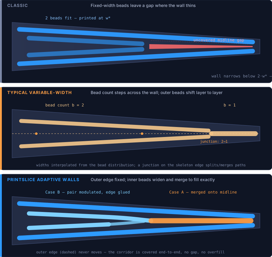
Adaptive Walls is PrintSlice's proprietary wall generator, designed from first principles and built in-house by 3D Laboratories. It sizes every inner bead to the exact local thickness of the wall, so tapers, fins and thin sections fill completely with no gaps and no overlaps, without the drawbacks common to variable-width walls. The outer wall is never resized, so visible surfaces stay smooth and uniform with no uneven layers or waviness, and regular walls are identical to classic output; the engine adapts only where the geometry demands it.

Where: Quality tab › Layers & Shells › Wall generator: Adaptive
See it: Preview a part with thin or tapering walls: inner walls widen and narrow to fill the section edge to edge.
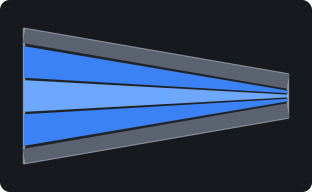
Bead widths follow the local wall thickness
FIG. 01Bead widths follow the local wall thickness
The same tapering wall, three approaches: only Adaptive Walls fills it exactly while holding the outer edge fixed
FIG. 01BThe same tapering wall, three approaches: only Adaptive Walls fills it exactly while holding the outer edge fixed
02 FlowDefault onInfill › Solid infill Novel algorithm · 3D Labs

Adaptive Solid Infill

Even fill from open areas into the tightest corners.

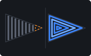
A novel fill algorithm developed by 3D Laboratories. Narrow solid regions such as ribs, webs and thin bridges between walls are filled with rings that follow their shape, all the way into the narrowest point, instead of a fixed crosshatch that stops short. Solid layers end exactly at the inner edge of the walls, and flow eases off on short lines and into tight corners and tapers, so edges and corners finish flat instead of building up excess material.

Where: Infill tab › Solid infill generator: Adaptive (default) and Extra deposit per line; tuned per material under Filament › Extra deposit calibration
See it: Preview a part with thin internal solid ribs: continuous, shape-following fill instead of a crosshatch.
Shape-following rings reach the narrowest point
FIG. 02Shape-following rings reach the narrowest point

Surfaces & seams

What you see and touch: skins, seams and the foundations beneath them.

Seams that disappear, skins that finish flat and top surfaces that start on solid ground.

PrintSlice Pro preview with a clip plane cut through walls, solid infill and supports
Preview · clip plane through walls, solid infill and supports
06 SurfaceQuality › Seam Novel algorithm · 3D Labs

Seam Track & Scarf Joint

Seams placed where they disappear, and blended where they show.

Seam Track chooses where each wall loop starts and ends, tucking the seam into a corner or aligning it along a clean straight line so it is hidden by the part's own geometry. The scarf joint then tapers the start and end of the loop into an angled overlap, replacing the familiar seam bump with a smooth, continuous wall. Weld-matched scarf sizes that overlap to how quickly the material cools.

Where: Quality tab › Seam card › Seam position and the scarf joint controls
See it: Zoom into a wall seam in Preview: a scarf shows as an angled overlap rather than a blob.
Seam aligned into the inside corner
FIG. 06Seam aligned into the inside corner
Scarf: the loop start ramps under its end
FIG. 07Scarf: the loop start ramps under its end
03 GeometryAutomatic Novel algorithm · 3D Labs

Predictive Scaffolding

Top surfaces that start on solid ground.

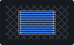
PrintSlice looks ahead to where a solid top surface will begin over sparse infill. In the layers just beneath it, a supporting ring grows early, so the first solid layer lands on a firm edge instead of an open lattice.

Where: Automatic; no setting required.
See it: Step through the sparse layers just below a solid island in Preview: a thin ring appears ahead of the surface.
An early ring supports the edge of a top island
FIG. 03An early ring supports the edge of a top island
04 GeometryAutomatic Novel algorithm · 3D Labs

Bridge Deck

Solid fill anchored into the infill below.

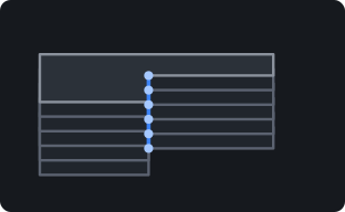
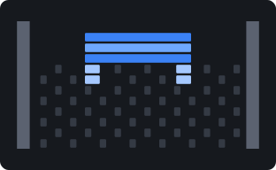
Where a solid region sits on sparse infill, its lines run crosswise to the lattice beneath and weld onto it. Every line end lands on material rather than finishing in mid-air over an open cell, so the deck stays flat and anchored.

Where: Automatic; no setting required.
See it: Preview a solid island over sparse infill: anchored line ends with no curl.
Solid lines laid across and anchored to the lattice
FIG. 04Solid lines laid across and anchored to the lattice
05 SurfaceAutomatic

Monotonic Line Skins

Clean, consistent top and bottom surfaces.

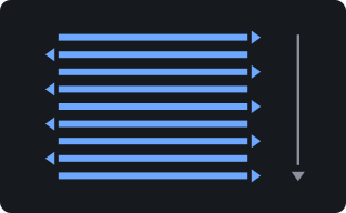
Top and bottom solid surfaces are printed as separate back-and-forth lines with no connecting travel between them. With no connector segments crossing the surface, the finished skin is flatter and cleaner, with a uniform line pattern from edge to edge.

Where: Automatic on every top and bottom surface.
See it: Any top or bottom surface in Preview: individual lines, direction alternating each pass.
Separate lines, one sweep order, no connectors
FIG. 05Separate lines, one sweep order, no connectors

Thermal & bonding

Heat modeled through the whole print to protect every layer bond.

A transient heat-transfer model of the whole build, and the features that act on what it predicts.

PrintSlice Pro preview of a tool tray in PEEK colored by predicted warp risk
Preview · Warp risk · tool tray, PEEK, 3D Labs HTX profile
07 ThermalAutomatic Novel algorithm · 3D Labs

Thermal Intelligence

See layer bonding before you print.

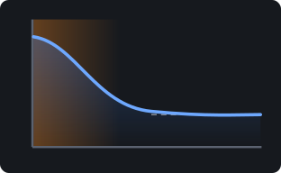
PrintSlice runs a transient heat-transfer model of the whole build before you print. Every island is solved as a one-dimensional column through the layers with an implicit (backward-Euler) scheme, driven by the real toolpath timeline: bead temperature, layer clock, bed and chamber boundaries, and forced convection from the part-cooling fan. Its heat-transfer treatment follows published FFF models (Ramos 2022/2023; Costa 2015; Zhang 2022) and was validated against instrumented builds: a thermocouple-instrumented PLA block reproduced to 11 °C RMS, a plate-heated block to 1.2 °C. From that thermal history it predicts interface weld temperature, softening and sag, crystallization and warp, per bead and per layer.

Where: Runs automatically; material set under Temperature tab › Thermal card › Material class
See it: Preview › Coloring › Thermal Analysis: Interface/Substrate temperature, Layer bond quality, Sag risk, Time to solidify, Crystallinity, Warp risk.
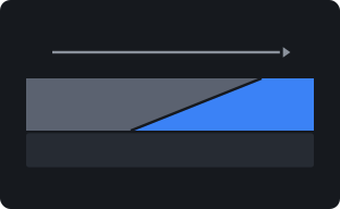
Interface temperature settles with height above the bed
FIG. 08Interface temperature settles with height above the bed
08 ThermalPreview › Coloring Novel algorithm · 3D Labs

Thermal Analysis Views

The physics of every layer, made visible.

Seven predictive views, each grounded in published polymer physics. Interface temperature: the weld temperature where a fresh bead meets the layer below, taken as the mean of melt and substrate temperature from the infrared weld-zone measurements of Seppala et al. (NIST, 2016-2017). Substrate temperature: how far the layer below has cooled when the next layer reaches it, the quantity that governs interlayer diffusion. Layer bond quality: the interface temperature placed against the material's weld window, informed by bond-formation studies of PEEK overprinting (Humbert et al., 2024) and FDM bonding quality (Sun et al., 2008). Sag risk: whether a layer can carry the next before it is loaded, from a WLF load-bearing temperature and, for semicrystalline polymers, a crystallinity percolation threshold. Time to solidify: the seconds each layer needs to become load-bearing. Crystallinity: the degree of crystallization each layer reaches along its actual thermal history (Nakamura kinetics). Warp risk: strain locked in below the glass transition plus retained crystallization shrinkage, acting through the bed's heat-affected zone (decay length after Compton et al., 2017) and a beam-curvature lever arm scaled by part geometry, rank-ordering published warp series (Armillotta 2018; Ramian 2021; Mittal 2024).

Where: Preview › Coloring › Thermal Analysis section
See it: Switch between the views on the same slice to see cause and effect: substrate cooling, interface temperature, then bond quality.
Interface, substrate and bond: one thermal history, three views
FIG. 09Interface, substrate and bond: one thermal history, three views
09 ThermalTemperature › Thermal guard

Thermal Guard

Automatic temperature control that protects every layer bond.

A closed-loop nozzle-temperature planner that uses the thermal model as its plant. Where a layer is predicted to stay too soft, it schedules a lower setpoint ahead of time, leading the hot-end's thermal lag so the change lands on the right layer, and re-solves the model to verify each step before it is written. Every setpoint passes one clamp: the material's processing window, a melt floor derived from the flow the layer demands, and a bounded total excursion. Your own temperature rows always take precedence.

Where: Temperature tab › Thermal card › Thermal guard: Off / Advise / Inject
See it: The Thermal Analysis coloring modes; with Inject, temperature commands appear in the exported G-code at the scheduled layers.
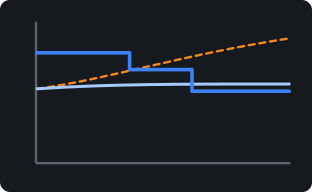
Stepped setpoint holds the interface temperature level
FIG. 10Stepped setpoint holds the interface temperature level
10 AnalysisRefine stage

Refine Stage

An engineering review of every slice.

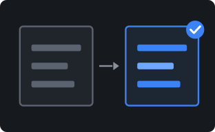
After every slice, Refine turns the thermal analysis into decisions. Each finding (sag bands, weak interfaces, heat build-up, warp risk) is matched with the levers that address it: nozzle schedule, layer time, speed, fan, bed, chamber and brim. Every recommendation is evaluated as a counterfactual, re-solving the thermal model with the change applied, so it is offered only when the physics shows a real gain, with the before/after numbers alongside. Nothing is applied until you accept it.

Where: The Refine stage, alongside Prepare and Preview on the canvas.
See it: Open Refine after a slice: recommendation cards with before/after tables.
Before/after comparison, applied on approval
FIG. 11Before/after comparison, applied on approval
11 ThermalMaterial › Cooldown

Controlled Cooldown

A stress-relieving finish for warp-prone parts.

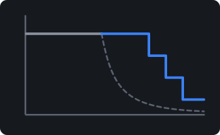
An end-of-print thermal schedule for semicrystalline and high-temperature polymers. Using non-isothermal Nakamura crystallization kinetics fitted to fast-scanning calorimetry (PEEK: Hamid & Kravchenko, CC BY 4.0; PEKK and CF-PEKK: Pérez-Martín et al.), PrintSlice holds the part warm long enough to complete crystallization and relax stress, then steps it down through the glass transition at a rate chosen to limit the thermal gradient. Emitted as plain temperature holds and steps that run on any firmware.

Where: Material Cooldown setting: Off / Auto / Custom; also offered as a Refine recommendation when it helps.
See it: Temperature holds and steps at the end of the exported G-code.
Warm hold, then a stepped cooldown
FIG. 12Warm hold, then a stepped cooldown

Thermal Intelligence

Seven views, one thermal history.

Switch between the views on the same slice to see cause and effect: substrate cooling, interface temperature, then bond quality. Preview › Coloring › Thermal Analysis.

01
Substrate temperatureHow far the layer below has cooled when the next layer reaches it.
02
Interface temperatureThe weld temperature where a fresh bead meets the layer below.
03
Layer bond qualityEach interface placed against the material's weld window.
04
Sag riskWhether a layer can carry the next before it is loaded.
05
Time to solidifyThe seconds each layer needs to become load-bearing.
06
CrystallinityThe crystallization each layer reaches along its real thermal history.
07
Warp riskLocked-in strain and shrinkage acting through the bed’s heat-affected zone.
Low riskCritical
PrintSlice Pro Refine stage with recommendation cards and before/after tables
Refine · recommendations evaluated as counterfactuals
  • Refine recommendations. Findings matched with the levers that fix them, each one tested as a counterfactual with before/after numbers.
  • Heated-envelope size guidance. How large a part your printer's heated envelope can print reliably in the material you have chosen.
  • Bond leveling. A speed lever that slows infill and solid fill on the layers predicted to bond weakly, keeping bond quality even up the part.
  • Thermal Guard. Nozzle setpoints scheduled ahead of hot-end lag and verified against the model before they are written.
  • Controlled Cooldown. Crystallization-aware holds and steps at the end of the print, on any firmware.

Supports & operations

Process-style control over every part and every height.

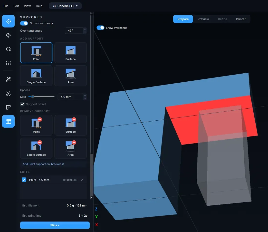
PrintSlice Pro support editor with overhang shading and the Point, Surface, Single Surface and Area tools

Supports that follow the part, placed exactly where you want them.

Contour supports follow the outline of the part instead of filling a block beneath it: a single-direction 45-degree body with one shell that you can squeeze off by hand, a dense crossed interface under the overhang, full-column expansion beyond the overhang edge and solid footing pads on the plate. Overhangs are shaded on the model at your chosen angle, and a placement editor adds or removes support by Point, Surface, Single Surface or Area, with every edit listed and reversible.

  • Single-direction 45-degree body, one shell, hand-removable
  • Dense crossed interface under the overhang
  • Full-column expansion past the overhang edge; solid footing pads
  • Add or remove: Point, Surface, Single Surface, Area; edits listed per object
PrintSlice Pro Height Range Wizard splitting a model into three height ranges

Process-style workflows per height range and per object.

Every setting, machine configuration included, lives in an operation. Give each object its own operation, or split a part at the heights where its settings should change with the Height Range Wizard: each range gets its own operation, a copy of the current one, ready to edit.

  • Operations per object
  • Operations per height range
  • Height Range Wizard
  • Machine settings travel with the operation
Contour supports following the outline of a part: a 45-degree single-shell body with a dense crossed interface and footing pads

Preview that shows the print, not just the path.

Color by feature type, speed, flow, or any of the thermal analysis views. Cut through the part with a clip plane to inspect walls, solid regions and supports layer by layer. A staged progress view shows each step of a multithreaded slice as it completes.

Also in the box

The controls a production slicer needs.

Auto-orient & arrangeParts placed and oriented on the plate automatically.
Fast multithreaded slicingSlicing runs across all cores, with a staged progress view that shows each step.
Rich preview coloringColor by feature type, speed, flow and the full set of thermal analysis views.
Pressure advanceSet per material and written for your firmware.
Per-feature line widthsIndependent widths for walls, infill, solid, top surfaces and supports.
Volumetric flow limitSpeeds capped to what the hot-end and material can melt.
Z-hopLift on travel, including hop over finished top surfaces.
Fan controlFan off for the first layer, fan hold and boost, and extra fan channels such as filters.
Top-layer extrusion multiplierTune the flow of the final visible surface on its own.

Printer compatibility

HTX out of the box. Marlin and Klipper machines by configuration.

Machine settings travel with the operation, so one process can be carried across a mixed fleet.

Supported out of the box

3D Labs HTX

Bundled printer profile and HTX material profiles for PEEK, PEEK-CF, PEKK, PEKK-CF, PEI, PSU, PA-CF, ABS/ASA, PP, TPU and PLA, with the heated chamber, part-cooling fan and HEPA filter channels already configured.

Supported

Marlin-based printers

Any Marlin-based machine: set the build volume, heaters, fans and start/end G-code once in the Machine settings, and every operation carries it.

Supported

Klipper-based printers

Any Klipper-based machine, with a Klipper-style start sequence and temperature waits written for its firmware.

Coming soon

Duet (RepRapFirmware)

Duet support is in development.

Research foundations

Grounded in published polymer physics.

The thermal model follows published FFF heat-transfer treatments and was validated against instrumented builds: a thermocouple-instrumented PLA block reproduced to 11 °C RMS, a plate-heated block to 1.2 °C.

  • Heat transfer in FFFRamos 2022/2023; Costa 2015; Zhang 2022
  • Weld-zone temperatureSeppala et al., NIST, 2016-2017
  • Bond formationHumbert et al., 2024 (PEEK overprinting); Sun et al., 2008
  • Warp and the bed heat-affected zoneCompton et al., 2017; Armillotta 2018; Ramian 2021; Mittal 2024
  • Crystallization kineticsHamid & Kravchenko (PEEK, CC BY 4.0); Pérez-Martín et al. (PEKK, CF-PEKK)

3D Labs Trusted By

Airgard KPD BlueHalo Simpson Strong-Tie Systems Integrated Chevron Apex Industries I-CAR Moog Advanced Technology and Research Corporation L3Harris Oak Ridge National Laboratory National Institutes of Health U.S. Department of Energy U.S. Army NASA

Talk to 3D Laboratories

Evaluate PrintSlice Pro on your own parts.

Send us a part and the material you print it in. We will slice it, walk through the analysis with your engineers, and configure your printers.

PrintSlice Pro beta program

Print with the engine before it ships.

The beta program is for engineers and labs printing PEEK, PEKK, PEI and other engineering materials. Members receive early builds as they are cut, talk directly to the engineers who build the slicer, and see their findings shape what gets built next.

Request a demo

What beta members get

01
Early buildsNew engine features and thermal views ahead of each release, delivered as offline installers.
02
Direct engineering contactYour questions and findings go to the people writing the code.
03
Roadmap inputYour parts and materials help decide what we build next.

Places are limited to what the engineering team can support directly. Signing up registers your interest; we confirm each place by email.

Account Menu $0